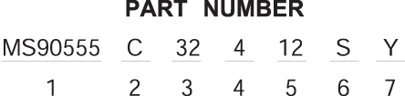
MS90555 designates wall mount receptacle (power source)
MS90556 designates straight plug
MS90557 designates cable connecting receptacle without coupling ring
MS90558 designates wall mount plug with coupling ring (equipment end)
Shell Finish
C (conductive) for AC or N (nonconductive) for DC circuit
Grounding Assemblies : Finish C
Shell Size
Current Rating Amps
Shell Master Key / Keyway Position
60Hz & 400Hz
1 Phase
3 Phase
2 Wire
3 Wire
3 Wire
3 Wire
120VAC
240VAC
120/240VAC
450/480VAC
120/208VAC
240/416VAC
277/480VAC
28
40
4(120')
5(135')
4(120')
4(120')
5(135')
6(150 )
32
60
4(120')
5(135')
4(120')
4(120')
5(135')
6(150 )
44
100
4(120')
4(120')
1(60)
4(120')
5(135')
6(150 )
52
200
4(120')
4(120')
5(135')
6(150 )
Non-grounding Assemblies : Finish Nv
Shell Size
Current Rating Amps
Shell Master / Key
Keyway Position
DC
2 Wire
28 VDC
28
60
N(105 )
32
100
N(105 )
44
200
N(105 )
52
N(105 )
Shell Size - related directly to current carrying capability.
Size 28 - 40 amperes
Size 32 - 60 amperes
Size 44 - 100 amperes
Size 52 - 200 amperes
Master Key / Keyway Position
N designates normal position. Positions 1, 4, 5 and 6 of the master key/keyway
prevent cross-mating of incompatible voltages. Refer to the adjacent illustration
Insert Arrangement
determined by connector size (current carrying capa-bility) and cable configuration
to be accommodated. Refer to pages 5 & 6
Contact Type
P for pin, S for socket. MS90555 and MS90557 are supplied with socket contacts
only. MS90556 and MS90558 are supplied with pin contacts only.
Alternate Insert Rotation
used to prevent cross-mating of incompatible frequencies. Absence of a letter
in this space indicates normal (0 ) position of the insert. Refer to page 7.


 Click to enlarge image
  Company